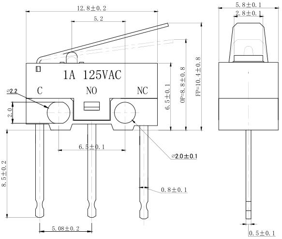
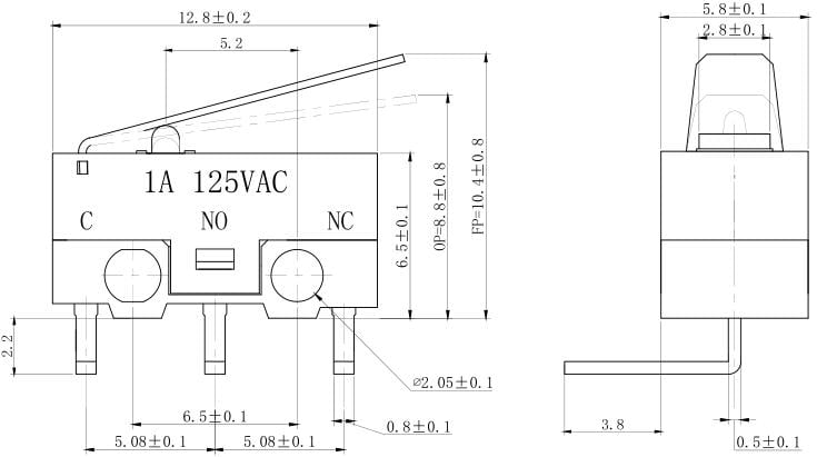
Sometimes I need to create and model my own KiCad components for use in my component library. For example, I found some cheap small microswitches on AliExpress that I am looking to use in SwarmBot, however, there was no existing KiCad Component in the library. I found an identical switch and a datasheet for the same size microswitch.
If I had not found the datasheet I could have built my library for the KiCad component using measurements taken using a pair of digital callipers. Having the callipers makes creating a 3D model for use in the KiCAD 3D viewer easier.
I use a mix of Fusion 360 and KiCAD for design, so I CADDed up the three flavours of microswitches Vertical, Lefthand right angle, and Righthand right angle. using the dimensions and land pattern from the datasheet:

The Procedure I followed in KiCad v5 was as follows:
Schematic Symbol:
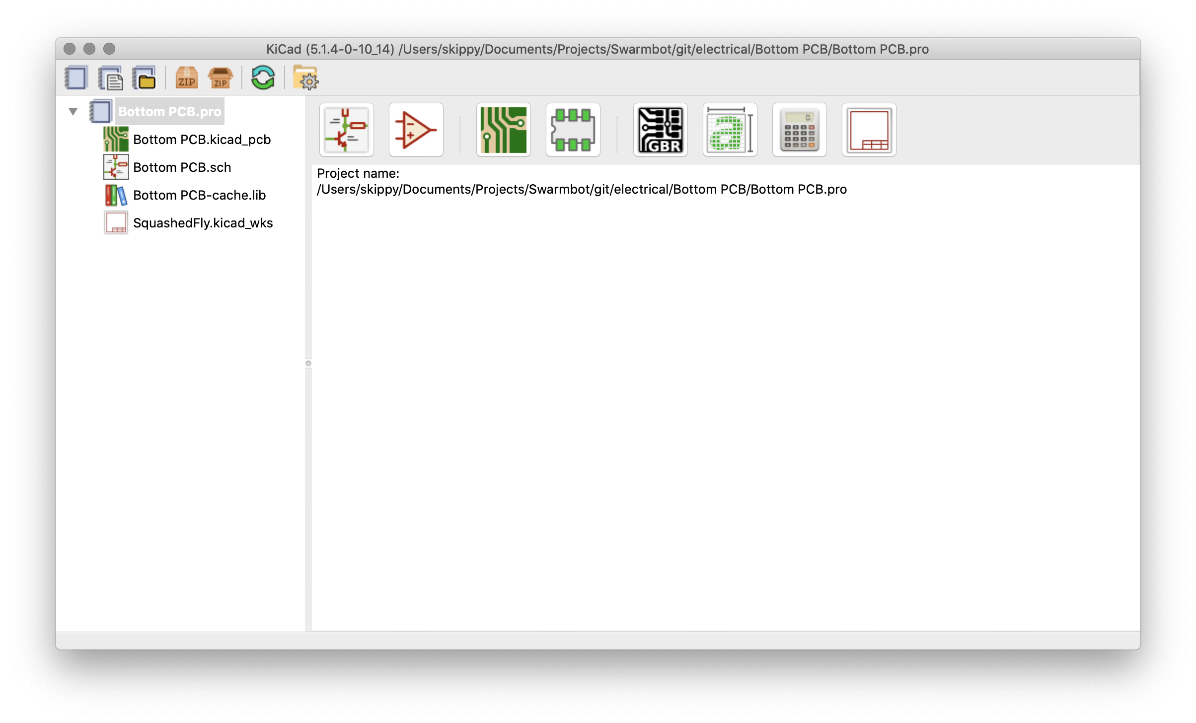
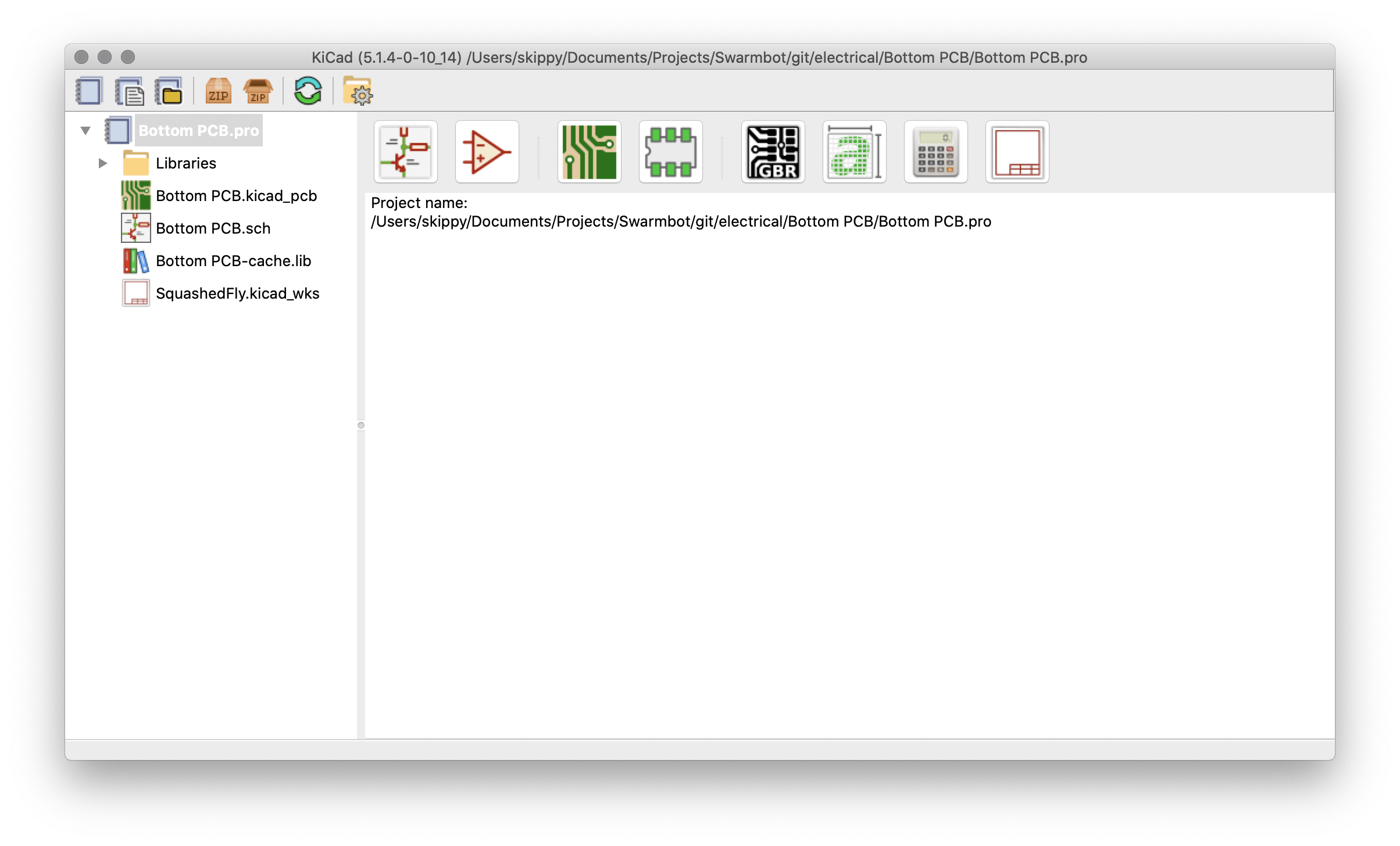
Open KiCad, into a project where you want to use the components.
Open ‘Symbol Editor’ » ‘File’ » ‘New Library’; I chose to put them into my project and make them a ‘Project Library’
‘Little Switch’ now appears on the left-hand side of the screen
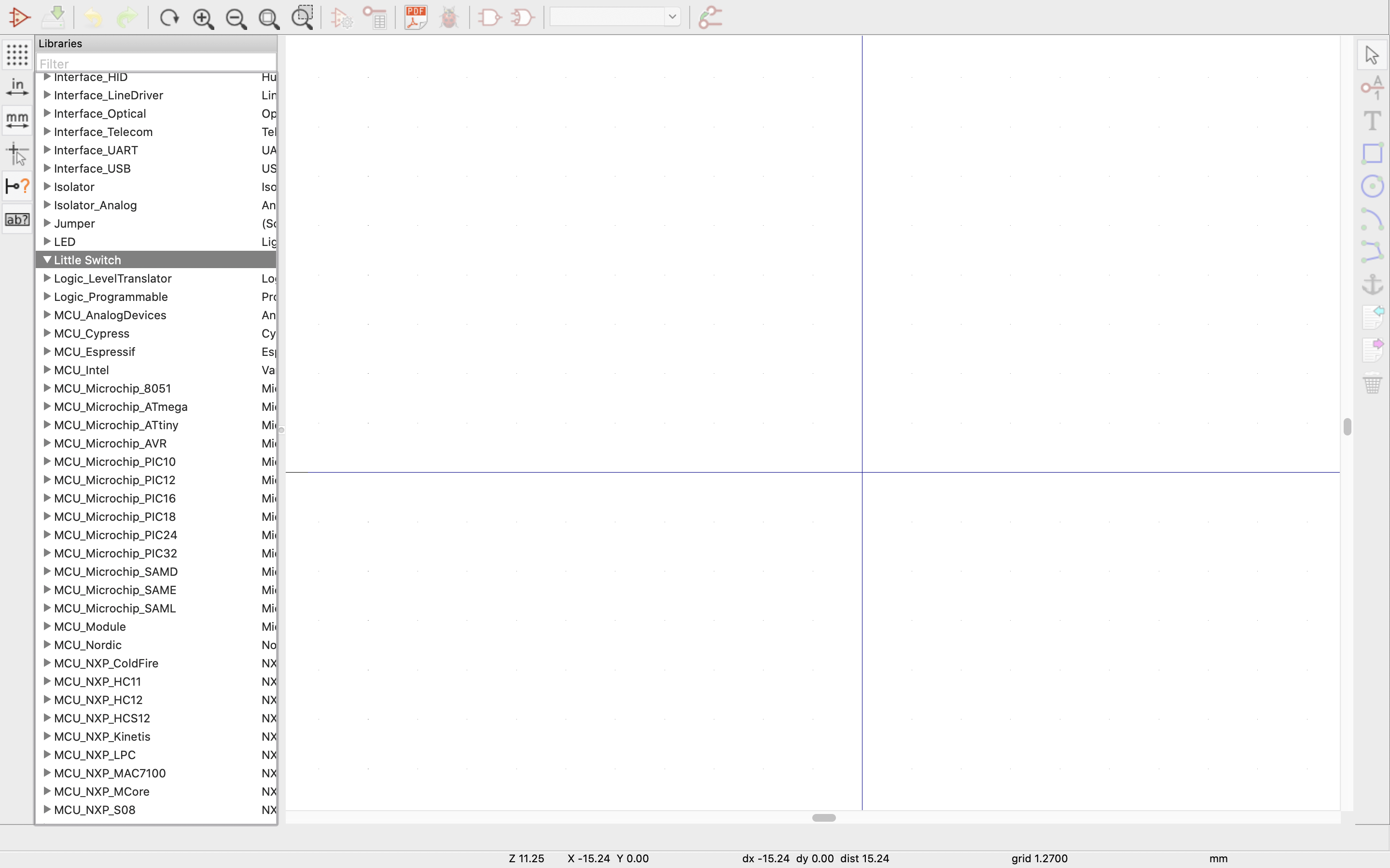
Schematic Symbol Library editor
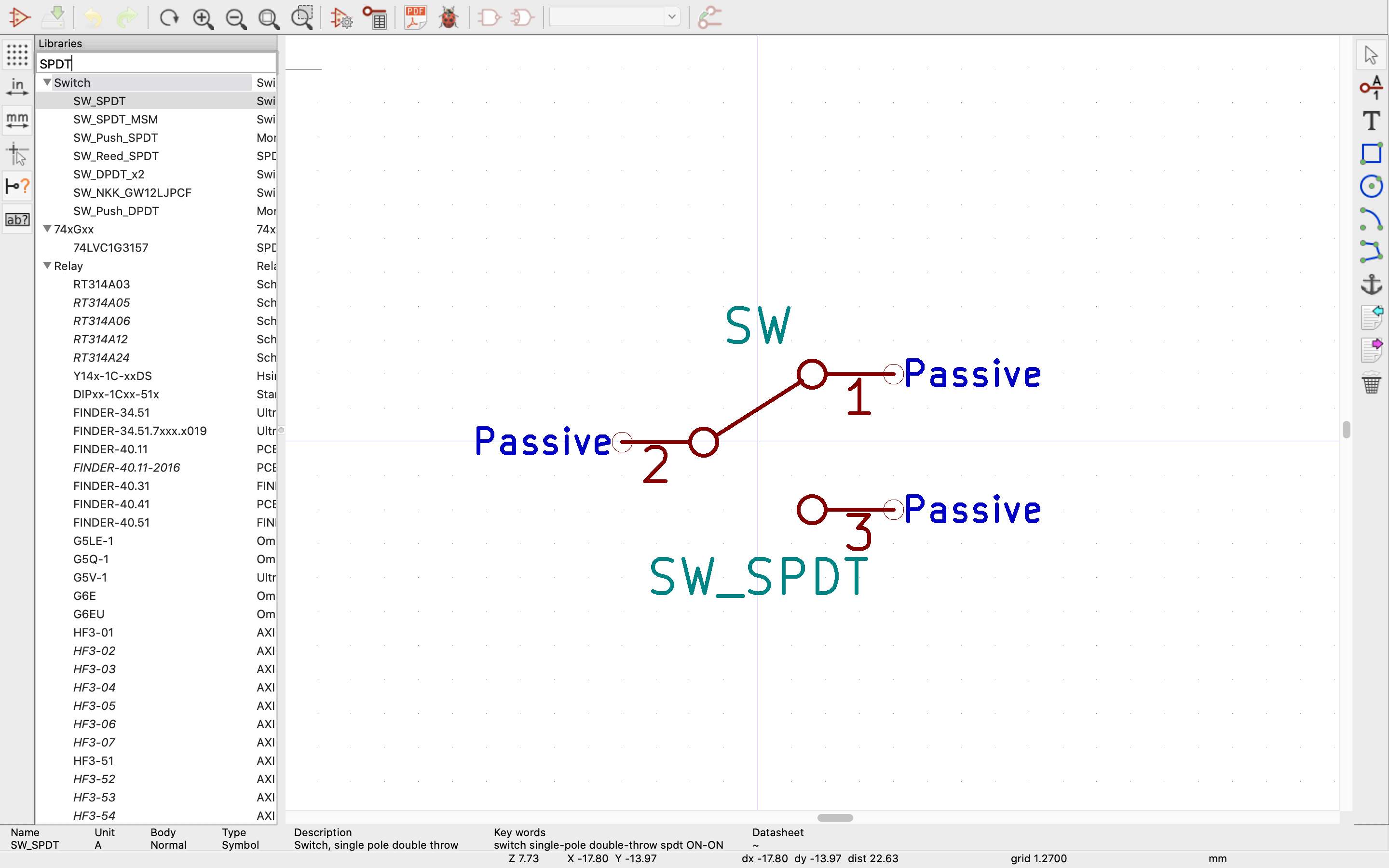
Since a SPDT switch is a common item, I ran the search for that rather than drawing my own this time, and double clicked to load the first one to check that I was happy with it.
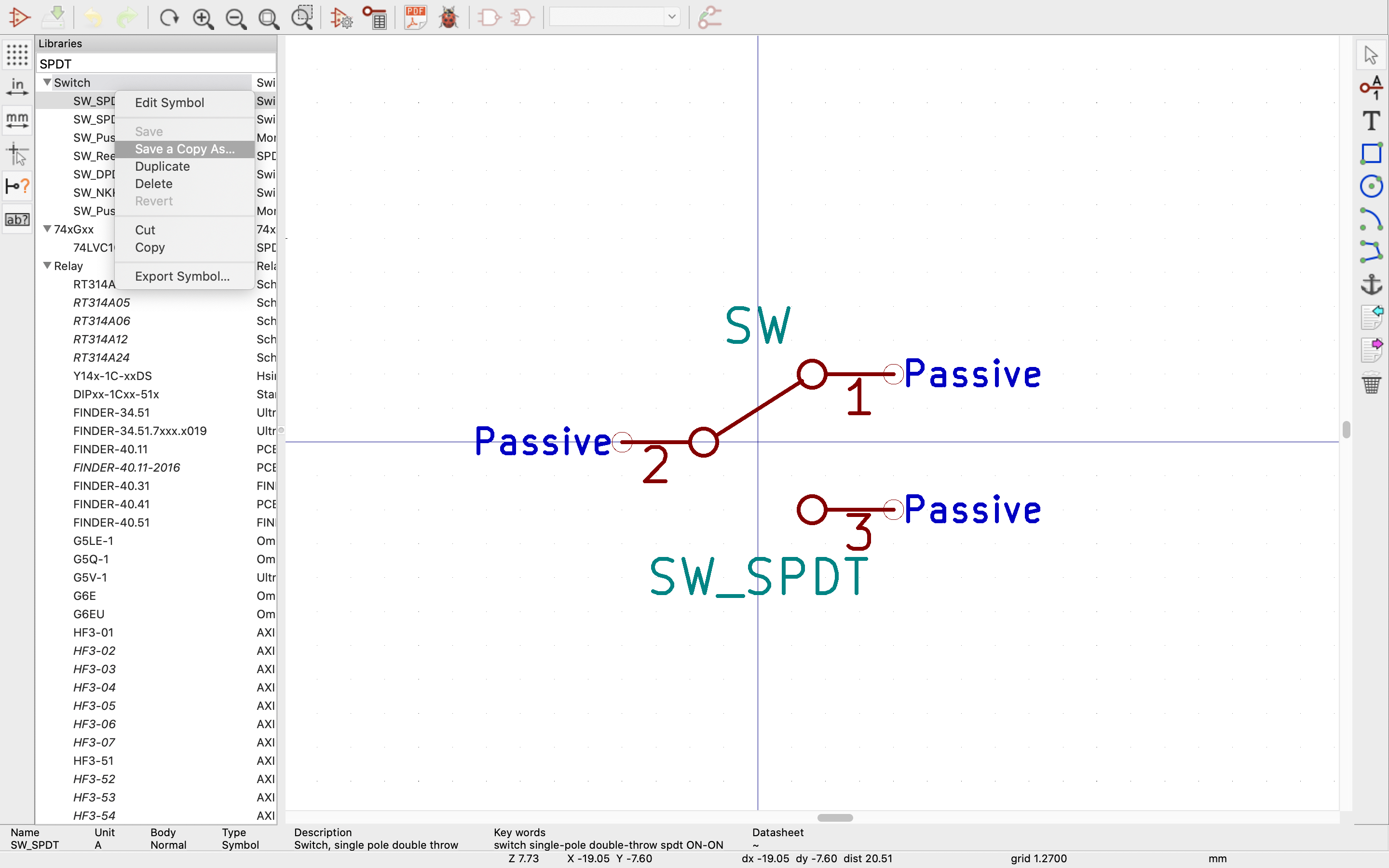
Right-click to save a copy
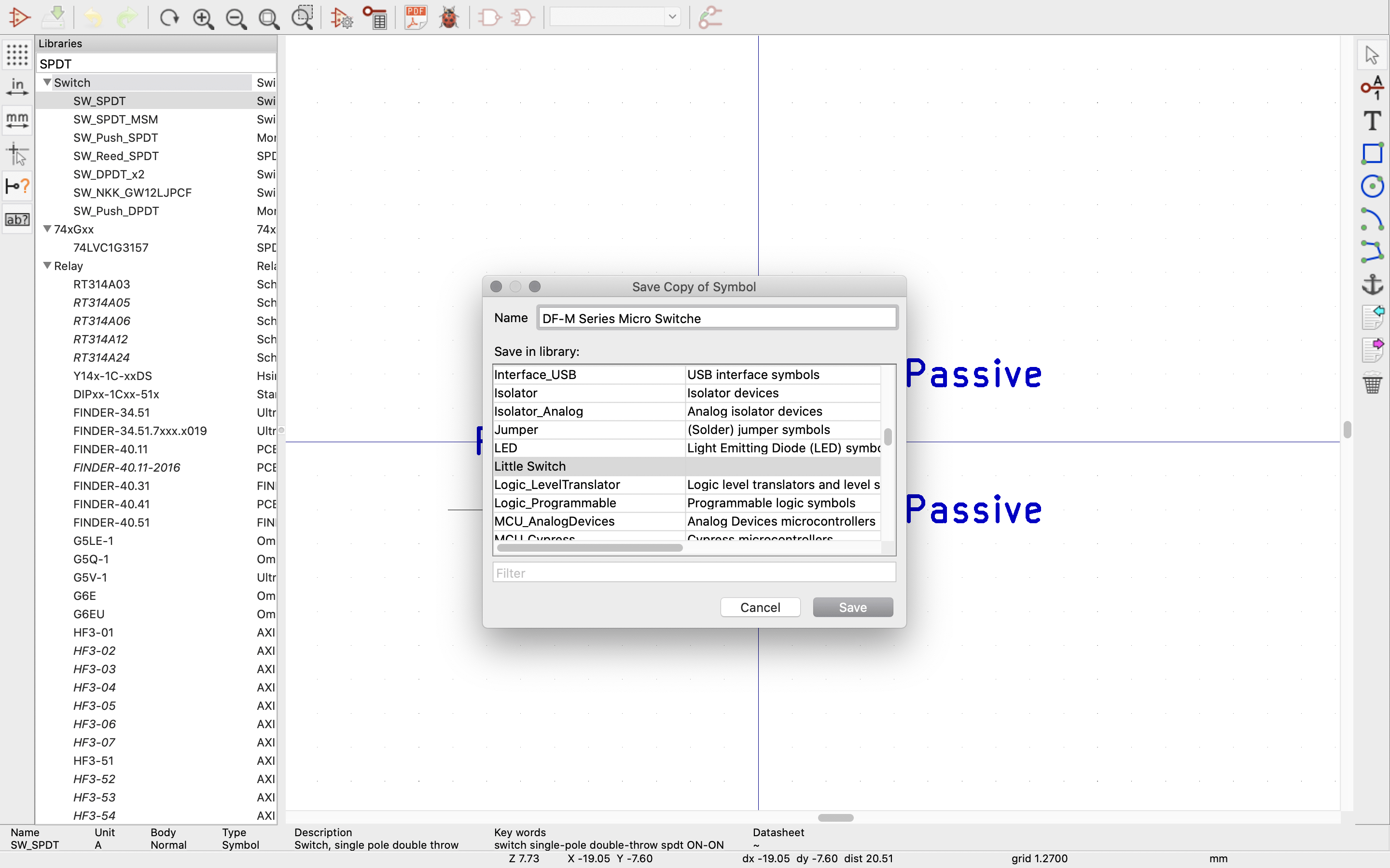
I selected the library I wanted to save the file in, and since the Microswitch is a ‘DF-M Series Micro Switch’ I saved it as such
KiCad Component PCB Footprint:
Back to the front screen (still inside your project):
Like before you will want to save the new library: ‘Footprint Editor’ » ‘File’ » ‘New Library’ Find ‘Little Switch’ on the left-hand side and right-click» ‘New Footprint’:

Since the first one I am going to draw is the ‘A Type‘ I have chosen to call it that,

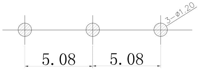
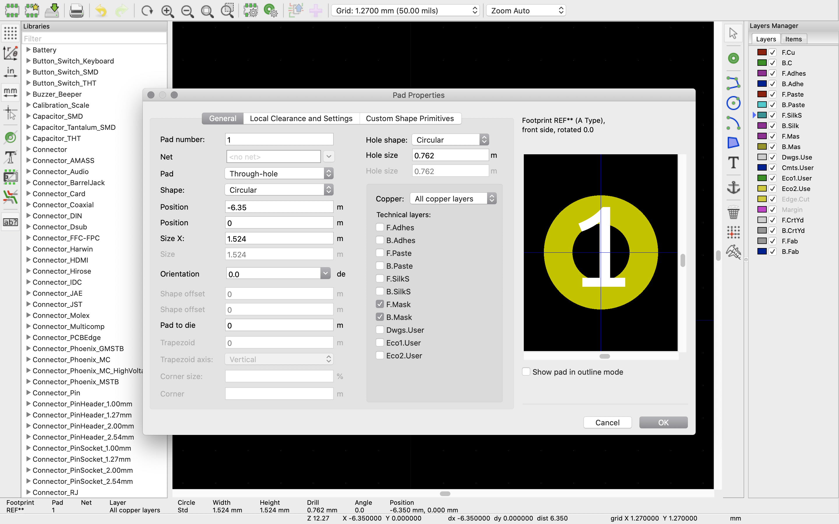
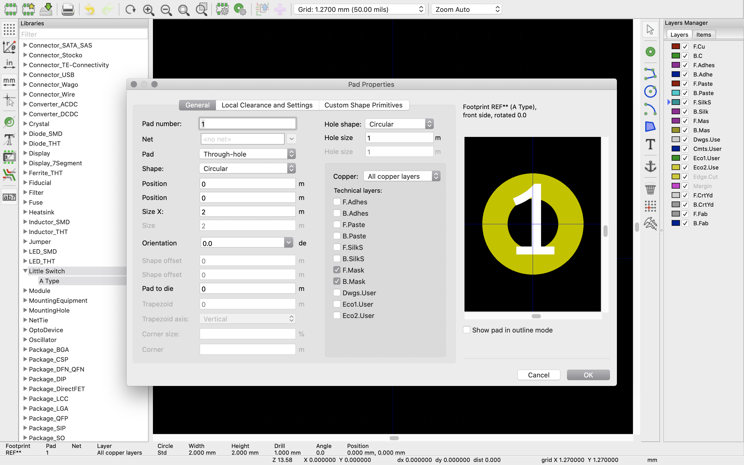
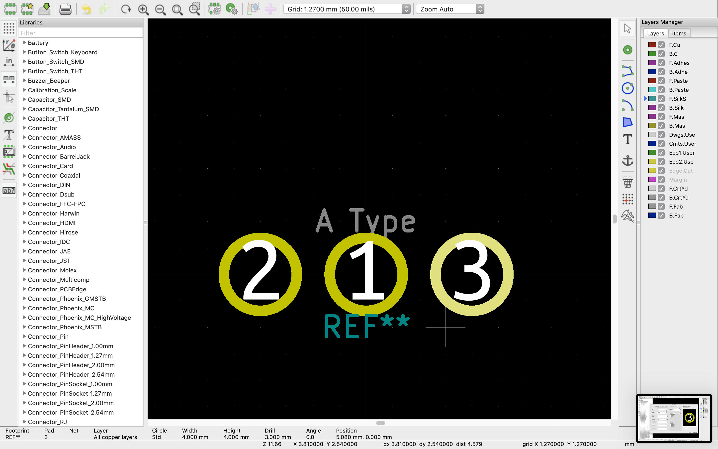
The following gets auto-populated on the screen: Select the ‘Pad tool’ and place down three pads in roughly the right place, I have also moved the auto-populated parts as well.

Using the data sheet land pattern as a guide
I now use the pad » right click » ‘properties’ menu to fine-tune the pad’s details:
Check the layout and mark it up:
A bit more drawing later, using the ‘Add Graphics Line’ on the silk screen layer we have now got the A-Type drawn approximately as per the datasheet

Now we can use the A-Type we have drawn to start working on the other two, Type C and Type D. Right-click on ‘A Type’ » ‘Save as’
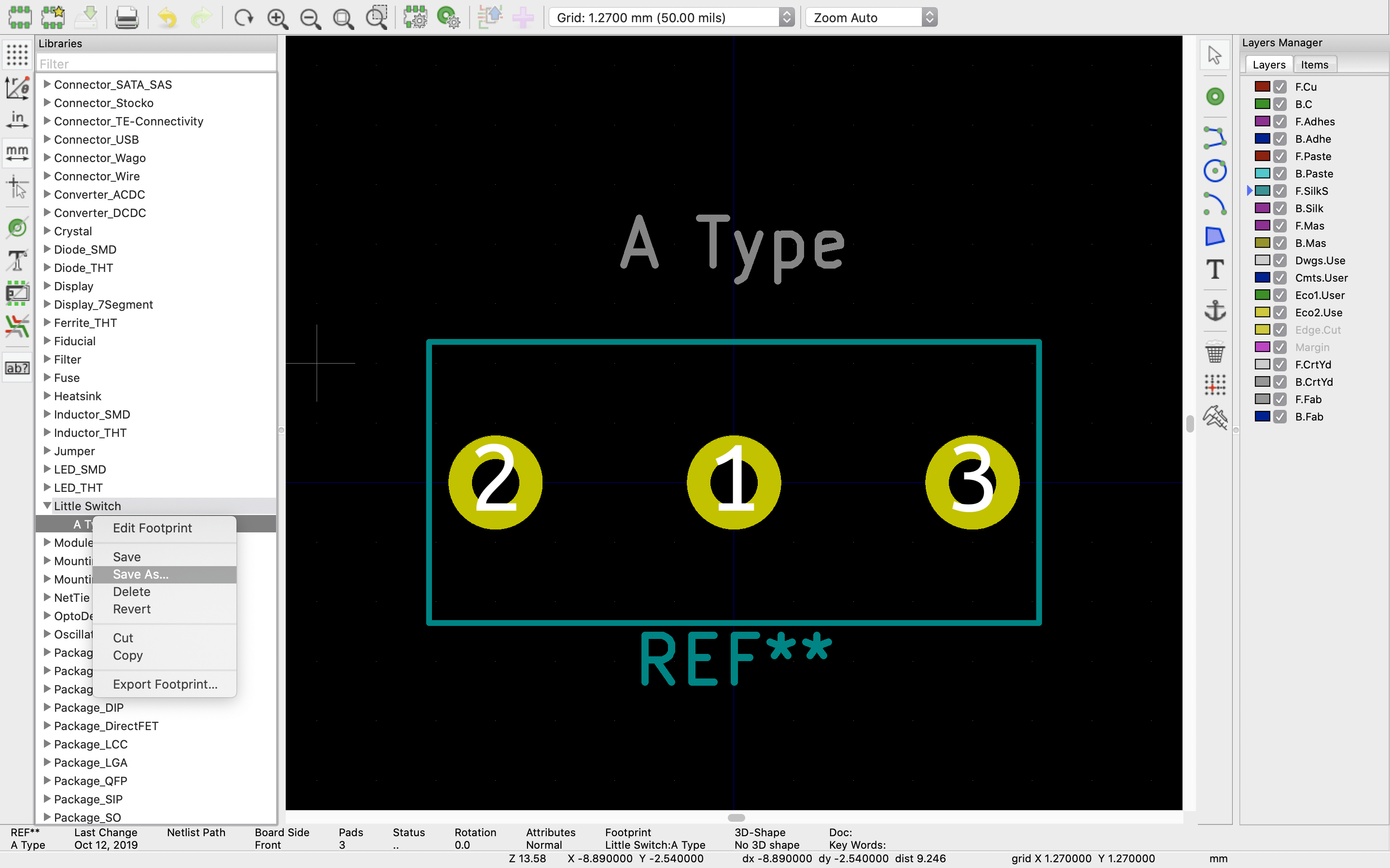

For the Type C, and D we will mainly just want to move the outline box to indicate the way the switch lays.
Since this post is getting a bit long, I will write another about how to import the 3D model, and make that all pretty!


